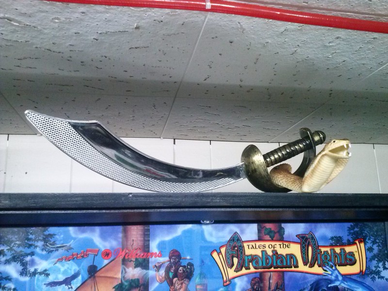
Ever since I got my TOTAN I've always wanted to make an interactive sword topper for it but didn't want to spend $275 for the one on PDI's site. A new spooky Halloween costume store opened up a few weeks ago near my work so I thought I would check it out and see what I could use to decorate my gameroom. I stumbled across a similar sword used for the topper on PDI's site so I bought a few of them. I also had a rubber snake lying around so figure I would integrate it in with the topper. I plan on lighting it up from inside the belly with a fading red LED from cointaker later and tie into the skill shot light.
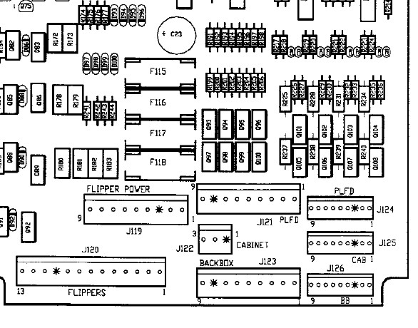
This mod will be completely plug and play once we make the harness and here is the pin outs and hook up points. It can easily be reversed or removed without having to cut into the existing wiring. On your WPC Power board look on the lower right corner and look for J121 and J125.
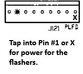
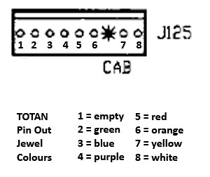
J125 is where you will be using the 9 Pin connector to tap into each jewel to light up for the topper. Take note of the Legend on the bottom for each corresponding jewel color pin out. If you want to get fancy you can buy different color wires to match up the harness and the jewels otherwise just keep track of the 7 wires when running to the bulb sockets.
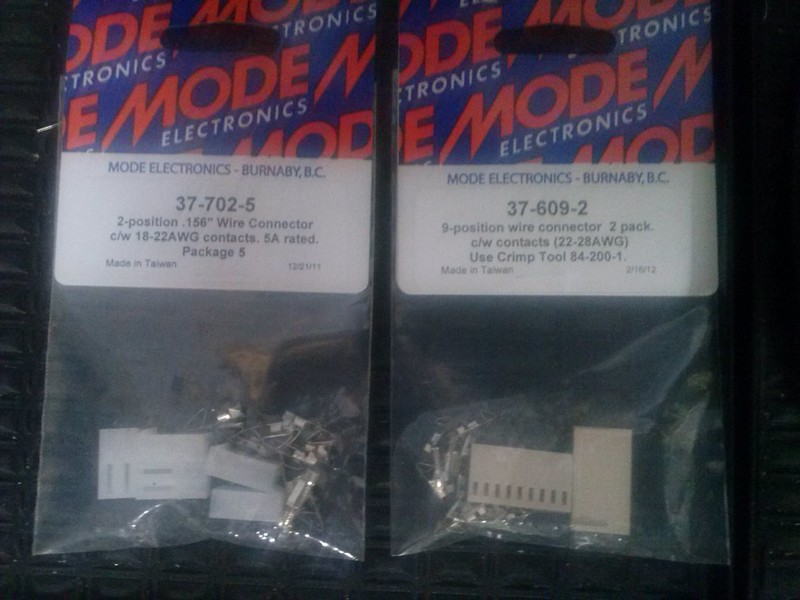
Now we will make a wiring harness and going to need some basic tools which most will already have if you do your own pin repairs such as a molex crimper, wire stripper, etc. I bought some connectors from my local electronics store or else you can order from an online vendor like Great Plains Eletronics.
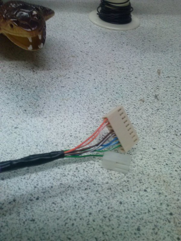
I didn't have enough wire left on my spool so I used cat5 network cable instead which I had tons lying around. It helped keep wiring organized and had exactly 8 color coded wires which was perfect for wiring up 7 jewels and 1 for power.
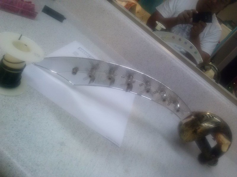
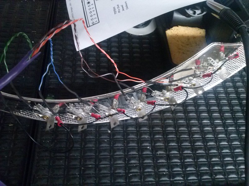
I ordered a bunch of #44 bulb sockets and some concave Ablaze LEDS to match each jewel color from Pinball Life. I measure and marked out 7 holes and drilled them out to insert the bulb sockets through.
I ran a daisy chain for the common power for each bulb and then soldered on a 1N4004 diode for each bulb socket.
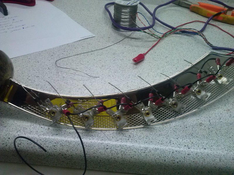
I stripped the other end of my cat5 wiring harness and ran each corresponding color on the other end of each diode. I twisted the wires and added a bit of solder to hold it in place to the diode and sealed it with some heat shrink tubing. Then used some zip ties to conceal some of the wiring behind the sword so not visible from the front side.
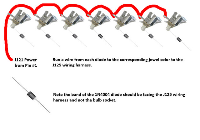
Keep in mind the band side of the diode should be facing away from the socket. I created a simple wiring diagram to illustrate this to make it more clear
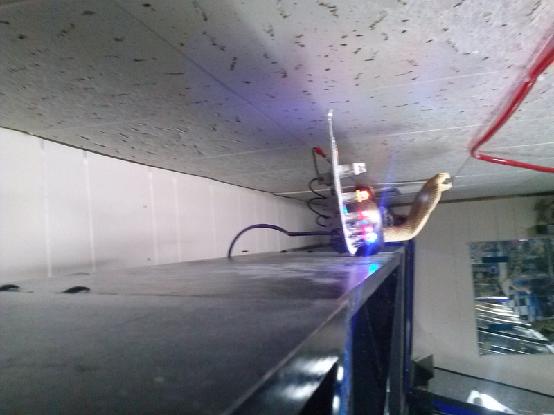
Now I mounted the topper and removed one screw on the mesh in the head and fed the harness through and connected everything up to the WPC power board.
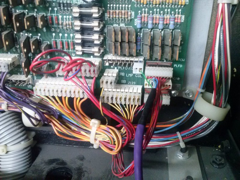
Just in case J125 has a plug on it you can move it up to the connector directly above it labelled "PLFD" or J124. If you want you can even connect up your topper J124 instead of J125 as they both do the same thing. It was almost as if Williams planned on having an interactive topper and had a pinout for it or maybe there was one?
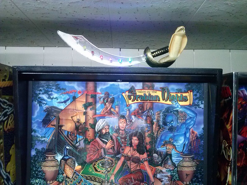
Here is a final pic of it installed as well as a short video I made of the topper in attract mode
https://www.youtube.com/watch?v=bCAKOet ... ature=plcp
Enjoy and any questions feel free to ask.
-Mike

This mod will be completely plug and play once we make the harness and here is the pin outs and hook up points. It can easily be reversed or removed without having to cut into the existing wiring. On your WPC Power board look on the lower right corner and look for J121 and J125.


J125 is where you will be using the 9 Pin connector to tap into each jewel to light up for the topper. Take note of the Legend on the bottom for each corresponding jewel color pin out. If you want to get fancy you can buy different color wires to match up the harness and the jewels otherwise just keep track of the 7 wires when running to the bulb sockets.

Now we will make a wiring harness and going to need some basic tools which most will already have if you do your own pin repairs such as a molex crimper, wire stripper, etc. I bought some connectors from my local electronics store or else you can order from an online vendor like Great Plains Eletronics.

I didn't have enough wire left on my spool so I used cat5 network cable instead which I had tons lying around. It helped keep wiring organized and had exactly 8 color coded wires which was perfect for wiring up 7 jewels and 1 for power.

I ordered a bunch of #44 bulb sockets and some concave Ablaze LEDS to match each jewel color from Pinball Life. I measure and marked out 7 holes and drilled them out to insert the bulb sockets through.

I ran a daisy chain for the common power for each bulb and then soldered on a 1N4004 diode for each bulb socket.

I stripped the other end of my cat5 wiring harness and ran each corresponding color on the other end of each diode. I twisted the wires and added a bit of solder to hold it in place to the diode and sealed it with some heat shrink tubing. Then used some zip ties to conceal some of the wiring behind the sword so not visible from the front side.

Keep in mind the band side of the diode should be facing away from the socket. I created a simple wiring diagram to illustrate this to make it more clear

Now I mounted the topper and removed one screw on the mesh in the head and fed the harness through and connected everything up to the WPC power board.

Just in case J125 has a plug on it you can move it up to the connector directly above it labelled "PLFD" or J124. If you want you can even connect up your topper J124 instead of J125 as they both do the same thing. It was almost as if Williams planned on having an interactive topper and had a pinout for it or maybe there was one?

Here is a final pic of it installed as well as a short video I made of the topper in attract mode

https://www.youtube.com/watch?v=bCAKOet ... ature=plcp
Enjoy and any questions feel free to ask.
-Mike
