• We have upgaded to the latest version of XenForum and the process finished without any errors!!!! Enjoy the new forum!

Solar Ride Help

azsiros

New Member
Dec 9, 2021
19
3
3
69
Ancaster, Ontario
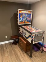
Hi there, I just joined this forum, I have a Gottleib Solar Ride pinball in need of repair, hoping that someone can assist.
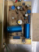
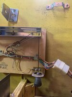
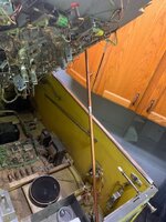
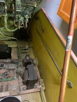
This was a machine I picked up from a relative wgo had it for years, it did work at one time but I guess it stopped working and was left as is for a long time. Before I powered it on I checked all the fuses and found a blown 10A fuse for the lightbox lamp(first fuse in the line of 5 fuses on the bottom board). I replaced the fuse and when powering on it doesn't blow any more fuses but I'm not getting any voltage out of the power supply board. The Power Supply A2 board has 12.1V and 14.7V coming in on the J1 connector(close enough to the 11.5 and 14 stated in the manual) but I don't get any voltages coming out on the J2 or J3 connectors. Of course my thought is to replace the power supply board, does anyone have any other advice, maybe what to check first before I spend my money on something I don't need?
 

azsiros

New Member
Dec 9, 2021
19
3
3
69
Ancaster, Ontario
Thanks for the quick reply and the great web site link, I never saw that before. From this I at least know that I have the later version power supply. I don't see any burned components on my board but the 2 transistors, one sticking out from the top and one from the bottom, don't have any bolts holding them down to the metal base (although they do have the mica insulators there). This certainly could be an issue if they need to be grounded to the metal base. your thoughts???
 

Attachments

  • IMG_0012.jpg
    IMG_0012.jpg
    134.3 KB · Views: 16
  • Like
Reactions: thc666

sylvain

Active Member
Apr 27, 2013
209
75
28
Ottawa, ON
The prior owner or tech did not re-assemble the power supply correctly.

The two 'transistors' sticking out (one is actually a voltage regulator) must NOT be electrically connected to the metal plate,
that is why there is a mica isolator under each. The metal plate is used as a heat-sink (through the mica isolators)
to cool those components. There should be screws, a plastic 'washer/isolator', lockwasher and nut on each 'transistor'
to apply gentle pressure between the component, mica and metal plate for cooling (but without grounding them to the plate!).

I assume the power supply will need to be disassembled again to properly repair it anyway.
There might be bad component(s) that would need to be tested to confirm if they are good or bad
(transistor, capacitor, etc.; often bad components 'look' fine), and/or cold solder joints under header pins
or at the two pins for the large transistor under the plate feeding through the board.

There are good web sites out there for safety and guidance on repairing pinballs and their boards,
and specifically for Gottlieb System 1 power supply

If you are not too sure about troubleshooting and/or safely/properly repairing electronic boards,
purchasing a new replacement power supply might be a solution - although it would not fix wiring/connector issues.

Good luck !
 
  • Like
Reactions: thc666

azsiros

New Member
Dec 9, 2021
19
3
3
69
Ancaster, Ontario
Well I did buy and replace the power supply and it looks good. I finished the restoration with all new rubbers and trying to sort out why the drop targets don't reset now. The solenoid activates but doesn't seem to have enough lift to latch them back in place. I don't see any problem mechanically, the lift lever is not worn, not sure if adjusting the solenoid is the thing to do...?
 

sylvain

Active Member
Apr 27, 2013
209
75
28
Ottawa, ON
If the coil sleeve cleaning as suggested by luch above does not help,
The reset solenoid assembly for the drop targets can have its position adjusted via two screws on the drop target assembly cage. Easy to do with the machine unplugged, adjust the coil reset assembly so that it just clicks-in the drop targets up with the solenoid fully engaged into its coil. Then tighten the adjustment screws.

Also ensure the proper reset coil is installed - sometimes a prior owner might have replaced it with an incorrect replacement coil number, if it had burned in the past due to bad ground or a shorted drive transistor for instance.
Also make sure the driver board fingers (connectors) are clean, along with the pins inside the connector for it.
Make sure the machine is OFF before unplugging or replugging connectors.

Good luck!
 
Last edited:

azsiros

New Member
Dec 9, 2021
19
3
3
69
Ancaster, Ontario
Thanks! I noticed the solenoid mounting screws are already at the top of the opening for adjustment but I also noticed there is another set of threads halfway down the solenoid so I should be able to move the screws down into the middle of the adjustment slot to allow for more solenoid adjustment.
I'm concerned though that the targets have to lower enough to let the ball roll by so I guess there's not going to be much room for adjustment. There doesn't seem to be any play between the bar and fingers or any of the other mechanism as well. I'll try this solenoid adjustment today and let you know how it goes.
 

Attachments

  • Drop-Target.jpg
    Drop-Target.jpg
    72.6 KB · Views: 7

azsiros

New Member
Dec 9, 2021
19
3
3
69
Ancaster, Ontario
I took the solenoid off, cleaned the shaft and plastic bushing and put the mounting screws in the lower set of threads on the solenoid which gave me some room to adjust it higher. I probably didn't move it up more than 1/16" but that was enough, it seems to be resetting the targets reliably now. Thanks for the advice! Hoping you can take another minute to help me with my next question and a bigger issue...

Question - where do you put the ground wire on the cpu board? I've heard you can solder it to the A1J4-1 connector at bottom of board or you can connect to negative lead of C16 capacitor. Would either one work or is one a better choice than the other?

Next issue, and a bigger problem...I've noticed now that during middle of play the back display blanks out and the flippers stop working and then a second or two later the back score lights come back on as if it were powering up. During this time all the lights on the playfield are still on, so it's not a complete power reset. Once the back panel comes back on it's just like a fresh power on however, I have to press the play button to start the game all over again. I want to get these ground mods done before I go any further but doubt that the grounds will fix this problem.
Any ideas?
 
  • Like
Reactions: luch

sylvain

Active Member
Apr 27, 2013
209
75
28
Ottawa, ON
I took the solenoid off, cleaned the shaft and plastic bushing and put the mounting screws in the lower set of threads on the solenoid which gave me some room to adjust it higher. I probably didn't move it up more than 1/16" but that was enough, it seems to be resetting the targets reliably now. Thanks for the advice! Hoping you can take another minute to help me with my next question and a bigger issue...

Question - where do you put the ground wire on the cpu board? I've heard you can solder it to the A1J4-1 connector at bottom of board or you can connect to negative lead of C16 capacitor. Would either one work or is one a better choice than the other?

Next issue, and a bigger problem...I've noticed now that during middle of play the back display blanks out and the flippers stop working and then a second or two later the back score lights come back on as if it were powering up. During this time all the lights on the playfield are still on, so it's not a complete power reset. Once the back panel comes back on it's just like a fresh power on however, I have to press the play button to start the game all over again. I want to get these ground mods done before I go any further but doubt that the grounds will fix this problem.
Any ideas?
For your next issue - sounds like the Slam switch opens or is seen as opened intermittently by the machine.
Lots of info on the web on how to fix and/or adjust this (switch itself contacts pressure; finger connector/pins for cabinet switches connector on MPU). There is also a mod available (soldering a bridge on the MPU) to bypass that Slam switch if wanted. That switch is typically located inside the cash door panel,

Ground mod: John Robertson in Vancouver (flippers.com) has good info - it involves soldering some wires on the boards and tying them to a common ground.
 
Last edited:

azsiros

New Member
Dec 9, 2021
19
3
3
69
Ancaster, Ontario
I grounded the MPU, Driver and power supply boards. They pointed out 6 slam switches but I could only find 4 - one on the cash door, the hanging plumb bob one and the ball roll switch on the side, and a fourth under the playfield. I don't have one in the bottom or any in the back panel. The cash door and ball roll switches are closed, the plumb bob switch is good(open) and the one under the playfield is open. the score displays (as per the video) don't indicate any slam switch issue. I still get a reset of game in middle of play. I didn't connect the jumper around the C2 capacitor yet but have my doubts that I'm going in the right direction. I'll investigate some more and see what I can figure out. I would like to attach a video to show you but don't think that can be done, only jpeg files?
 

Attachments

  • Slam1.jpg
    Slam1.jpg
    90.7 KB · Views: 5
  • Slam2.jpg
    Slam2.jpg
    157.7 KB · Views: 6
  • Slam3.jpg
    Slam3.jpg
    120.9 KB · Views: 6

sylvain

Active Member
Apr 27, 2013
209
75
28
Ottawa, ON
The displays strobing all 0 on power-up is a good indication of the slam switch permanently opened.
I cannot recall what the displays show when a slam (not a tilt) switch opens during a game - the game reboots for sure.
I would still perform the slam mod to be sure if I were you.

Next: How well is the +5V adjusted on the power supply, and are the cabinet to power supply and power supply to MPU harnesses making good connection ? If connector pins are loose, corroded or weak pressure, it could cause issues too.

To make sure the issue is not mechanical, intermittent or cold solder joint/contacts, I typically use a wooden screwdriver handle and gently tap on connectors and boards with the machine on to see if taps/vibration can make the issue occur.
Make sure you do not use anything metallic in the machine or disconnect/reconnect connectors with power on!
 

azsiros

New Member
Dec 9, 2021
19
3
3
69
Ancaster, Ontario
I did find one issue when as I went through the shake test. The ball launch solenoid tripped off followed by the drop target solenoid. The contacts on the switch were too close together, I adjusted it and now that works fine. I guess the drop target solenoid is supposed to trip off when the ball launch solenoid activates since you starting with a new ball. I played 3 games and never got the reset as I did before. I don't think this would have been the cause of my resets, since it was an intermittent problem. I'll have to play some more games and see how it goes.
 

azsiros

New Member
Dec 9, 2021
19
3
3
69
Ancaster, Ontario
Here's another interesting issue I found regarding flippers...when testing the flippers, I fix the playfield in the lifted position(about 30 degrees from level) and when I move the right flipper back and forth from the top of the playfield, it sticks in the middle of it's travel. In fact, it sticks so much that I can hardly move it through it's travel. Now as I move the playfield lower it sticks less and less, and when the playfield is back in it's down position the flipper moves fairly smoothly back and forth. I haven't taken it apart yet but wonder if anyone has seen this before? I'm sure it needs a rebuild and hopefully it will fix it but wonder what specifically would create this kind of problem? I did remove the left flipper just for a cleaning, used APL and put it back together. It has 2 metal, curved shims on the shaft and seems to work fine. The right flipper that has the problem has no plastic shaft at the end but I heard that some people remove this to prevent any possible sticking. The middle flipper has a different solenoid, 01-1668, it's the green one in the photos. Shouldn't this be 17875 as well?
 

Attachments

  • Flipper-left.jpg
    Flipper-left.jpg
    125.5 KB · Views: 3
  • Flipper-middle.jpg
    Flipper-middle.jpg
    111.7 KB · Views: 3
  • Flipper-right.jpg
    Flipper-right.jpg
    119.4 KB · Views: 3

koji

Member
Jun 29, 2021
40
5
8
Surrey, BC Canada
Here's another interesting issue I found regarding flippers...when testing the flippers, I fix the playfield in the lifted position(about 30 degrees from level) and when I move the right flipper back and forth from the top of the playfield, it sticks in the middle of it's travel. In fact, it sticks so much that I can hardly move it through it's travel. Now as I move the playfield lower it sticks less and less, and when the playfield is back in it's down position the flipper moves fairly smoothly back and forth. I haven't taken it apart yet but wonder if anyone has seen this before? I'm sure it needs a rebuild and hopefully it will fix it but wonder what specifically would create this kind of problem? I did remove the left flipper just for a cleaning, used APL and put it back together. It has 2 metal, curved shims on the shaft and seems to work fine. The right flipper that has the problem has no plastic shaft at the end but I heard that some people remove this to prevent any possible sticking. The middle flipper has a different solenoid, 01-1668, it's the green one in the photos. Shouldn't this be 17875 as well?
Check the gap on the top side of the playfield, between the flipper and the PF. you want about a credit card width in it. I thought the bushing on that style of assembly would stick out slightly, but just make sure the flipper is not rubbing the PF at all.. that's my best guess.. basically, when you lift the PF on the prop rod, there is probably a bit of flex happening?
 

azsiros

New Member
Dec 9, 2021
19
3
3
69
Ancaster, Ontario
The gap seemed fine but you were right about the bushing - it was the wrong one. It was a very light metal bushing and too short. I bought a new plastic bushing for it, cleaned the solenoid and parts and now it is working great! There are 2 curved metal shims between the solenoid and plate which I guess is normal. The bushing now sticks out a little bit from the metal plate so I think it's all fixed! As long as I don't get any more intermittent issues cropping up, guess I'll just have to start playing it and see what happens. I'll post a picture once it's all together, right now I have the legs removed, it's on a table with wheels so I can easily move it around in my basement for repair. I also removed the isolation transformer (a Canadian thing). I've always used a copper (plumbing) pipe to prop the PF up while working on it. I don't see how the original metal prop works, it doesn't seem yo be long enough to do anything so I just use this copper pipe. I also had to tie the PF up in vertical position to my ceiling rafter in order to hold it there and remove the transformer at the back of the box. Is the PF supposed to stay in vertical position somehow?? I'll post some photos soon to show you what I'm talking about.
 

azsiros

New Member
Dec 9, 2021
19
3
3
69
Ancaster, Ontario
Here are some photos of what I was talking about. I don't know what use that original metal prop is, it's not long enough to support the playfield.
Soon it will be beside my Evel Knievel, was hoping to put it in the cottage but afraid of humidity...
 

Attachments

  • prop-rod.jpg
    prop-rod.jpg
    83.5 KB · Views: 2
  • prop-rod1.jpg
    prop-rod1.jpg
    72.6 KB · Views: 2
  • IMG_0715.jpg
    IMG_0715.jpg
    62 KB · Views: 2