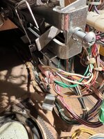
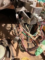
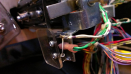
Alright, for anyone that owns or has owned a STTNG you likely have heard about the dreaded Aux8 PCB "tie back" wire along with all of the issues this game can have surrounding it. For those that have not heard about this particular issue, the coles notes are this...
STTNG has a LOT of parts stuffed into the game, and as such there are not enough transistors on the main driver PCB to control everything. What the designers came up with was a small auxilary driver PCB (which we all refer to as the Aux8 board) that is located in the upper right corner of the back box that gives these games the added transistors they need. You will find these on other widebody games of the same era like TZ and IJ etc, but this mod only pertains to STTNG! The Aux8 pcb must be connected to the 50V coil power at all times, or bad things happen... such as locked on coils and ultimately blown transistors.
The factory decided they would connect the Aux8 PCB to the 50V coil line by running a small wire down from the back box to the PF and attaching it to the 50V side of a coil, essentially "tieing it back" to the Aux8 PCB. Out of all the games that use an Aux8 pcb it is the only one that they chose to wire up this way, and I can only guess it was done this way to save money.
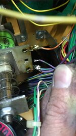
In this picture we have the underside of the STTNG drop target assembly located at the top of the PF, and I am holding the tie back wire in my fingers. You will notice it's purple with green stripes just like the larger AWG wires attached to the coil in the pic. Normally it is attached from the factory to the same coil lug with the other two purplpe/green wires, as this ensures the Aux8 PCB is connected to the 50V coil power. What ultimately happens is due to all of the vibration this mechanism has to endure, the smaller AWG tie back wire can and does break off of the coil lug, causing the Aux8 PCB to lose it's 50V connection. At this point one of the under PF subway divertors usually locks on because it's associated transistor has been damaged as a result of the failed tie-back. I have had the opportunity to work on at least 5 STTNG's over the years, and I've seen at least 3 of them with this coil literally melted.
Now for those that have done any sort of research on how to resolve this issue, there is no shortage of information out there on the subject. Unfortunately I was never overly satisfied with any of the recommendations, as it usually involved running a thicker extra wire down from the Aux8 PCB to another coil under the PF to double up the tie back in hopes to add some redundancy. What I've come up with below is my recommendation to solve the tie back issue by keeping it super simple and keeping it all contained within the back box.
(PSA: AS WITH ANY MOD LIKE THIS, ANYONE THAT ATTEMPTS THIS DOES SO AT THEIR OWN RISK! I CANNOT BE RESPONSIBLE FOR ANYONE ELSE'S WORK!)
Parts / Tool you will need;
-Wire cutters / Stripper
-Crimping Tool
-1pc trifuricon pin
-3 Position 0.156" Molex Connector
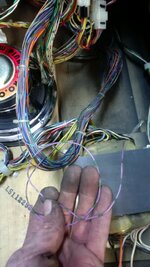
First, start by disconnecting the tie back wire from the coil under the PF and begin to pull it back out of the harness.
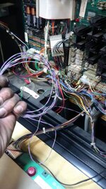
Continue to pull the tie back wire out of the harness all the way up into the back box. As you can see there is quite a bit of wire.
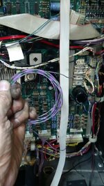
Pull the tie back wire up and out of the harness all the way back to the Aux8 pcb. Here I have it all coiled up nicely to show you roughly how much wire there is between the Aux8 PCB and the PF. Think of all the potential places this wire could fail over the years!
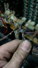
Locate header J108 on the main driver PCB, which is along the top edge about dead center. Now run the tie back wire you've pulled back from the Aux8 PCB to the J108 header on the driver PCB and cut the excess off, making sure you leave at least a few extra inches. Then strip the end of the tie back, and crimp a trifuricon pin to the end.
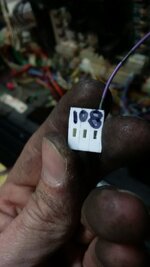
Install the freshly crimped pin into the 3 position Molex connector as shown, making sure you install it in the left most position of the connector.
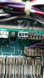
Then connect the terminated tie back wire/connector to J108 on the driver PCB as shown making sure the wire is on the left most pin. (which is Pin 1 of that connector)
That's it, you're done! By doing this you have essentially done the EXACT same thing the factory has done by running that long wire down to the drop target coil, but this connection is more robust saving your Aux8 and subway coils from self-destructing.
D.
STTNG has a LOT of parts stuffed into the game, and as such there are not enough transistors on the main driver PCB to control everything. What the designers came up with was a small auxilary driver PCB (which we all refer to as the Aux8 board) that is located in the upper right corner of the back box that gives these games the added transistors they need. You will find these on other widebody games of the same era like TZ and IJ etc, but this mod only pertains to STTNG! The Aux8 pcb must be connected to the 50V coil power at all times, or bad things happen... such as locked on coils and ultimately blown transistors.
The factory decided they would connect the Aux8 PCB to the 50V coil line by running a small wire down from the back box to the PF and attaching it to the 50V side of a coil, essentially "tieing it back" to the Aux8 PCB. Out of all the games that use an Aux8 pcb it is the only one that they chose to wire up this way, and I can only guess it was done this way to save money.

In this picture we have the underside of the STTNG drop target assembly located at the top of the PF, and I am holding the tie back wire in my fingers. You will notice it's purple with green stripes just like the larger AWG wires attached to the coil in the pic. Normally it is attached from the factory to the same coil lug with the other two purplpe/green wires, as this ensures the Aux8 PCB is connected to the 50V coil power. What ultimately happens is due to all of the vibration this mechanism has to endure, the smaller AWG tie back wire can and does break off of the coil lug, causing the Aux8 PCB to lose it's 50V connection. At this point one of the under PF subway divertors usually locks on because it's associated transistor has been damaged as a result of the failed tie-back. I have had the opportunity to work on at least 5 STTNG's over the years, and I've seen at least 3 of them with this coil literally melted.
Now for those that have done any sort of research on how to resolve this issue, there is no shortage of information out there on the subject. Unfortunately I was never overly satisfied with any of the recommendations, as it usually involved running a thicker extra wire down from the Aux8 PCB to another coil under the PF to double up the tie back in hopes to add some redundancy. What I've come up with below is my recommendation to solve the tie back issue by keeping it super simple and keeping it all contained within the back box.
(PSA: AS WITH ANY MOD LIKE THIS, ANYONE THAT ATTEMPTS THIS DOES SO AT THEIR OWN RISK! I CANNOT BE RESPONSIBLE FOR ANYONE ELSE'S WORK!)
Parts / Tool you will need;
-Wire cutters / Stripper
-Crimping Tool
-1pc trifuricon pin
-3 Position 0.156" Molex Connector

First, start by disconnecting the tie back wire from the coil under the PF and begin to pull it back out of the harness.

Continue to pull the tie back wire out of the harness all the way up into the back box. As you can see there is quite a bit of wire.

Pull the tie back wire up and out of the harness all the way back to the Aux8 pcb. Here I have it all coiled up nicely to show you roughly how much wire there is between the Aux8 PCB and the PF. Think of all the potential places this wire could fail over the years!

Locate header J108 on the main driver PCB, which is along the top edge about dead center. Now run the tie back wire you've pulled back from the Aux8 PCB to the J108 header on the driver PCB and cut the excess off, making sure you leave at least a few extra inches. Then strip the end of the tie back, and crimp a trifuricon pin to the end.

Install the freshly crimped pin into the 3 position Molex connector as shown, making sure you install it in the left most position of the connector.

Then connect the terminated tie back wire/connector to J108 on the driver PCB as shown making sure the wire is on the left most pin. (which is Pin 1 of that connector)
That's it, you're done! By doing this you have essentially done the EXACT same thing the factory has done by running that long wire down to the drop target coil, but this connection is more robust saving your Aux8 and subway coils from self-destructing.
D.

