So this one will be a first for me... in that I was out at a service call last night working on a reset issue in a Twilight Zone. Now that in and of itself is not new, anyone that has been into pinball for any legth of time should know that Twilight Zone is just one of those games that can be a nightmare when it comes to reset issues. It will be a first for me in the way I chose to combat the problem, and I'm very interested to see how this plays out long-term.
Pat Lawlor was given carte blanche when he designed TZ due to his previous smash hit Addams Family, and he pretty much threw in everything but the kitchen sink. As such this game has a lot of toys and mechanisms which wreaks havoc on the game's 5V section of the power supply (it doesn't have a lot of headroom). In this particular instance the game was completely fine and played pretty well, that is until you made it to Lost In The Zone and the game would reset almost every time. Before I was called in to help the owner decided to try one of those Kahr WPC Power "Fix" Daughter Boards, and just as one of my other clients experienced the board failed not long after it was installed which made the game completely unplayable. Once removed the game booted and played but still reset during LITZ.
On arrival first things first, take my DMM and measure the 5V rail on the driver PCB at TP2 when the game is in attract mode... ( I actually measured all of the other voltages on the driver and all were well within spec)
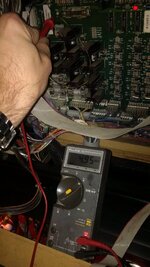
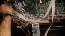
As you can see it's sitting at 4.95V. Now for most games this isn't *THAT* bad, but that voltage will fluctuate during game play and you can bet the voltage is slightly lower at the MPU once it crosses over through all the connectors... (dreaded "Z" connector in this game too)
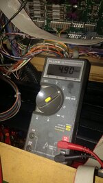
And here is the 5V rail measured off of pin 36 of the game ROM. Again, it's not *THAT* low and to be honest there are many games that will work just fine at this voltage but remember it will fluctuate during game play... and with the 10lbs of crap stuffed into the 1lb box that is TZ it's just not good enough!
I reseated all of the connectors between the driver PCB and the MPU, including both sides of the "Z" connector, and no change in voltage at the MPU. Reseated the J101 & J102 connectors, with no change in voltages. At this point I begin to look the driver over and notice that BR1 & BR2 have already been replaced at some point, but the C5 cap had not. I also noticed that the J101 A/C input connector responsible for the 5 and 12V on the right side of the driver PCB has a burnt connector. At this point I decide it best to pull the driver, and I replace the C5 cap and the J101 header. Where the connector is burnt the header has seen a lot of heat and should also be replaced to avoid future issues. For good measure I replace the C2 cap by the 12V regulator as well, as this part is now failing more often due to age and I don't want a call-back because of this part. I then replace the J101 connector with all new trifuricon pins and housing, and re-install the PCB to test the 5V rail... unfortunately with the same results. (5V was measuring no change)
At this point the next likely culprit is the 5V regulator, which is the LM323K mounted in the pirple heatsink.
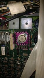
Now I've had to replace one or two of these lately to get a game's 5V rail back up to spec, and I'm lucky enough to have a bunch in my parts stash. These are getting somewhat difficult to find now they are no longer being made, so depending on where you buy from these can be expensive. (digikey is currently charging $37 US each for them!) The good news is there is an alternate option available from EzSBC.com
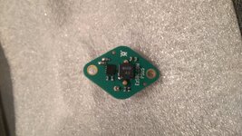
This is what I meant by a first for me. I picked up a couple of these just to try out, but up to now have not had any reqirement to do so. Normally I would just install one of the stock LM323K parts I have, but figure where this is going into a TZ, this would be the absolute PERFECT time to test one of these out! I say this because unlike the original part, this one actually has an adjustment potentiometer (you can just barely see it in the above pic - bottom center of the PCB) so I am able to dial in the output voltage. Being a TZ, I want to make sure the 5v rail at the MPU is at the very least 5.00V during game play.
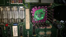
Pull the driver out, desolder the old LM323K and isntall the new EzSBC regulator making sure the nut on the upper right side of the part is not touching the small SMT capacitor that is unfortunately very close to it. Toss it in the game, but before I power the game up I disconnect the MPU power, as well as the flipper and coil connectors from the driver just in case there is an issue with the replacement regulator. This way if something does go wrong it *should* be contained to the driver PCB.
Power the game up, and all looks good so far. Initially the 5V rail was still sitting around 4.95V at TP2 so I power the game down and adjust the wee tiny trim pot a touch clockwise, flip the game on and test again to find my 5V is now sitting at 5.08V. PERFECT! Reconnect the MPU and the coil connectors, power the game up and test the voltages....
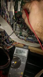
As you can see TP2 is now measuring 5.04V with the game in attract mode.
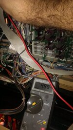
And the MPU measures 4.99V flickering up to 5.00V, which is EXACTLY where I wanted everything to be. To make sure everything was good we started a game and I measured TP2 and then pin 36 on the game ROM and got the exact same readings so we proceeded to put the game into LITZ mode and this time no resets.
HUZZAH!
D
Pat Lawlor was given carte blanche when he designed TZ due to his previous smash hit Addams Family, and he pretty much threw in everything but the kitchen sink. As such this game has a lot of toys and mechanisms which wreaks havoc on the game's 5V section of the power supply (it doesn't have a lot of headroom). In this particular instance the game was completely fine and played pretty well, that is until you made it to Lost In The Zone and the game would reset almost every time. Before I was called in to help the owner decided to try one of those Kahr WPC Power "Fix" Daughter Boards, and just as one of my other clients experienced the board failed not long after it was installed which made the game completely unplayable. Once removed the game booted and played but still reset during LITZ.
On arrival first things first, take my DMM and measure the 5V rail on the driver PCB at TP2 when the game is in attract mode... ( I actually measured all of the other voltages on the driver and all were well within spec)

As you can see it's sitting at 4.95V. Now for most games this isn't *THAT* bad, but that voltage will fluctuate during game play and you can bet the voltage is slightly lower at the MPU once it crosses over through all the connectors... (dreaded "Z" connector in this game too)

And here is the 5V rail measured off of pin 36 of the game ROM. Again, it's not *THAT* low and to be honest there are many games that will work just fine at this voltage but remember it will fluctuate during game play... and with the 10lbs of crap stuffed into the 1lb box that is TZ it's just not good enough!
I reseated all of the connectors between the driver PCB and the MPU, including both sides of the "Z" connector, and no change in voltage at the MPU. Reseated the J101 & J102 connectors, with no change in voltages. At this point I begin to look the driver over and notice that BR1 & BR2 have already been replaced at some point, but the C5 cap had not. I also noticed that the J101 A/C input connector responsible for the 5 and 12V on the right side of the driver PCB has a burnt connector. At this point I decide it best to pull the driver, and I replace the C5 cap and the J101 header. Where the connector is burnt the header has seen a lot of heat and should also be replaced to avoid future issues. For good measure I replace the C2 cap by the 12V regulator as well, as this part is now failing more often due to age and I don't want a call-back because of this part. I then replace the J101 connector with all new trifuricon pins and housing, and re-install the PCB to test the 5V rail... unfortunately with the same results. (5V was measuring no change)
At this point the next likely culprit is the 5V regulator, which is the LM323K mounted in the pirple heatsink.

Now I've had to replace one or two of these lately to get a game's 5V rail back up to spec, and I'm lucky enough to have a bunch in my parts stash. These are getting somewhat difficult to find now they are no longer being made, so depending on where you buy from these can be expensive. (digikey is currently charging $37 US each for them!) The good news is there is an alternate option available from EzSBC.com

This is what I meant by a first for me. I picked up a couple of these just to try out, but up to now have not had any reqirement to do so. Normally I would just install one of the stock LM323K parts I have, but figure where this is going into a TZ, this would be the absolute PERFECT time to test one of these out! I say this because unlike the original part, this one actually has an adjustment potentiometer (you can just barely see it in the above pic - bottom center of the PCB) so I am able to dial in the output voltage. Being a TZ, I want to make sure the 5v rail at the MPU is at the very least 5.00V during game play.

Pull the driver out, desolder the old LM323K and isntall the new EzSBC regulator making sure the nut on the upper right side of the part is not touching the small SMT capacitor that is unfortunately very close to it. Toss it in the game, but before I power the game up I disconnect the MPU power, as well as the flipper and coil connectors from the driver just in case there is an issue with the replacement regulator. This way if something does go wrong it *should* be contained to the driver PCB.
Power the game up, and all looks good so far. Initially the 5V rail was still sitting around 4.95V at TP2 so I power the game down and adjust the wee tiny trim pot a touch clockwise, flip the game on and test again to find my 5V is now sitting at 5.08V. PERFECT! Reconnect the MPU and the coil connectors, power the game up and test the voltages....

As you can see TP2 is now measuring 5.04V with the game in attract mode.

And the MPU measures 4.99V flickering up to 5.00V, which is EXACTLY where I wanted everything to be. To make sure everything was good we started a game and I measured TP2 and then pin 36 on the game ROM and got the exact same readings so we proceeded to put the game into LITZ mode and this time no resets.
HUZZAH!
D

