If anyone has a classic Bally or Stern title in their collection at any point, one of the easiest and most important things to check is the high-voltage section on the solenoid driver board for the correct voltage. (assuming your displays are working) The reason this is so important these days is to avoid burning up your displays, which can be difficult and costly to replace.
The HV section generates 240VDC for the displays, but they only require 190VDC to operate correctly and this is accomplished by a voltage adjustment potentiometer. There are a small number of components in the HV section, and I have found the weakest link in the chain here is this pot. Given the age of these and the cheap quality used by the factory, you will often find these have failed. When this happens the circuit was designed to continue working so the game was still able to operate on location, but as you can guess it pegs the display voltage at the max 240VDC and will severely shorten your plasma displays life. Toss your DMM on VDC, black lead to ground and red lead to TP2 which should read anywhere between 150 & 190VDC and TP4 which should read 240VDC. (please take care when poking around in the HV section, as 240VDC will give you a pretty good bite)
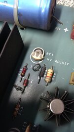
This picture is a perfect example as to why the HV section in my Centaur 2 failed;

This pot has the entire wiper section completely missing, so no adjusting this bad boy...
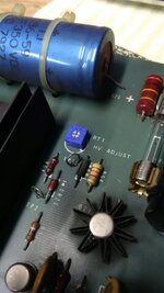
And what it looks like after replacing the pot with a new higher quality 25K pot;

Now, there are other components that can fail in the HV section but I've found that if TP2 is out of spec and/or nonadjustable the culprit is *usually* this pot.
D
The HV section generates 240VDC for the displays, but they only require 190VDC to operate correctly and this is accomplished by a voltage adjustment potentiometer. There are a small number of components in the HV section, and I have found the weakest link in the chain here is this pot. Given the age of these and the cheap quality used by the factory, you will often find these have failed. When this happens the circuit was designed to continue working so the game was still able to operate on location, but as you can guess it pegs the display voltage at the max 240VDC and will severely shorten your plasma displays life. Toss your DMM on VDC, black lead to ground and red lead to TP2 which should read anywhere between 150 & 190VDC and TP4 which should read 240VDC. (please take care when poking around in the HV section, as 240VDC will give you a pretty good bite)
This picture is a perfect example as to why the HV section in my Centaur 2 failed;

This pot has the entire wiper section completely missing, so no adjusting this bad boy...
And what it looks like after replacing the pot with a new higher quality 25K pot;

Now, there are other components that can fail in the HV section but I've found that if TP2 is out of spec and/or nonadjustable the culprit is *usually* this pot.
D
Last edited:
