• We have upgaded to the latest version of XenForum and the process finished without any errors!!!! Enjoy the new forum!

Devils Dare

Vengeance

Well-Known Member
Nov 14, 2012
1,990
139
63
Keswick, ON
Brought this game home Tuesday, didnt have time to unload and setup till yesterday:

11830742_10155808172950251_909055469_n.jpg


Found a perfect shape 30 year old batter still attached to the CPU, don't see that to often, it's gone now though:

11846570_10155819162905251_5028444774899448235_n.jpg


This has been one of the few times in a long time I've gone to pickup a cheap project and it was really easy to get it up and running. I think it was literately just a trough switch as I threw in an extra pinball and the machine started playing.

11846371_10155819228425251_1458294122_n.jpg


I found one broken wire in and connector on in the head, so repinned that and the sounds and speech cam to life. But have since stopped working again.

But it plays without issue, going to re-rubber it, wax it up and get it playing real nice today, also dig into the sound issue a bit more. Hearing the sounds and speech work perfect lead me to believe that it must just be a connector thing. So I'll have to repin the edge connector. along with a few others and do the ground mods and rebuild the power supply to make it reliable.
 
  • Like
Reactions: brad808

mwong168

Administrator
Staff member
Nov 14, 2012
6,682
1,452
113
46
Toronto
Nice score and Doug looked at this game over a year ago but the owner was pretty firm on his asking despite the machine being non working. After looking at the seller's pics again when he got home he suspected the slam tilt switch might have been the cause of the game not booting up and displaying all zeroes on all 4 displays. Glad it was a simple fix Adam.
 

Vengeance

Well-Known Member
Nov 14, 2012
1,990
139
63
Keswick, ON
Just think it was not having all the balls in the trough.

For the sound had it going again today so definitely connector related.

Going to replace this guy

d661dd606332afa7e35a822fcacbae40.jpg


This guy

2e315105d0905569a0d288d7b343a2ee.jpg


And this guy

6ea542de5f272581c9ec909c590ad25a.jpg


Sent from my SGH-I337M using Tapatalk
 

Vengeance

Well-Known Member
Nov 14, 2012
1,990
139
63
Keswick, ON
and now I've made it worse, cant get the sound working at all now.

I think I may have screwed up a wire or two on the connector to the sound board. I didn't crimp them well enough and they poped out on me after I was done, I may have messed up the order.

Of course since it's a Gotllieb and Steve Young is a dick, I can't check the manual or schematic to verify. So I have to either pony up or find someone with a devils dare so I can verify the wire colors on the pin out.
 

Vengeance

Well-Known Member
Nov 14, 2012
1,990
139
63
Keswick, ON
So I hot a copy of the manual (Thanks Randy!)

If I put -12 v on pin 4

9fa8b2ab4f7ecedb4b996cc93770b11c.jpg


I've probably fried something haven't I?

Sent from my SGH-I337M using Tapatalk
 

Vengeance

Well-Known Member
Nov 14, 2012
1,990
139
63
Keswick, ON
Well its not working, Doug thinks I may have fried the LM193

Just waiting on my new Hakko FR300 to remove the chip
 

flyer666

Member
Nov 16, 2012
157
12
18
Kitchener, Onatrio
Test it..this op amp chip should read infinite or open between 1,2 and 3...6,7 and 8

Better yet put a scope on pin 1 and 2 to see if there is a signal in then check pin 3 to see if there is signal out

Lastly, you can put voltage on 1 and 2 and see if there is voltage on pin 3....no more than 5 volts.


You will get the same results on the 2nd set of pins
 
Last edited:
  • Like
Reactions: brad808

Vengeance

Well-Known Member
Nov 14, 2012
1,990
139
63
Keswick, ON
Test it..this op amp chip should read infinite or open between 1,2 and 3...6,7 and 8

Better yet put a scope on pin 1 and 2 to see if there is a signal in then check pin 3 to see if there is signal out

Lastly, you can put voltage on 1 and 2 and see if there is voltage on pin 3....no more than 5 volts.


You will get the same results on the 2nd set of pins
Your gonna need to dumb that down a bit for me :)

I get the basics, I was able to accurately test the voltages on the connector pins.

But I'm not quite grasping how to test the chip.

I don't have access to an oscope either.

Sent from my SGH-I337M using Tapatalk
 

Menace

Well-Known Member
Staff member
Nov 14, 2012
2,440
255
83
Santiago de Aurora
If the whole game is not working now then it's likely more than just the LM193 that's pooched as that's just the lamp driver section. If all your power supply voltages are good and the game isn't booting, you're going to need to do some pretty heavy diagnostics on the MPU with a logic probe or o-scope to figure out what's going on.

D
 

Vengeance

Well-Known Member
Nov 14, 2012
1,990
139
63
Keswick, ON
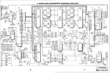
So here is the full schematic for the Devils Dare sound board.

so you can see:

Pin 1 has +12v
Pin 3 has -12V
Pin5 has +5V
Pin 10 has +30V

All of these voltages measure fine with the connector off of the sound board.

When I was crimping the connector, I did a shitty job and some of the wires fell out on me, I got confused on what went where and accidentally switched the wire for Pin3 with Pin4

I discovered this as a result of measuring the voltages and found -12V on pin 4 rather than Pin3.

Now I'm just trying to figure out what I've fucked up.

DevilsDare sounds Board.jpg
 

Menace

Well-Known Member
Staff member
Nov 14, 2012
2,440
255
83
Santiago de Aurora
Without a logic probe or o-scope you'll likely never figure out where the issue is, just the nature of sound PCB's. You need to start by verifying the sound PCB CPU is running and work your way out from there.

D
 

Vengeance

Well-Known Member
Nov 14, 2012
1,990
139
63
Keswick, ON
Without a logic probe or o-scope you'll likely never figure out where the issue is, just the nature of sound PCB's. You need to start by verifying the sound PCB CPU is running and work your way out from there.

D

I've got a crappy logic probe
 

flyer666

Member
Nov 16, 2012
157
12
18
Kitchener, Onatrio
Your gonna need to dumb that down a bit for me :)

I get the basics, I was able to accurately test the voltages on the connector pins.

But I'm not quite grasping how to test the chip.

I don't have access to an oscope either.

Sent from my SGH-I337M using Tapatalk

While game is off

Instead of checking voltages your checkings Ohms
should read infinite or open between 1,2 and 3...6,7 and 8
put one lead on 2 and the other on 3 check it for infinite or open and so on
Logic probe will work fine while the game is on you should get a signal whether high low or what ever on three pins per set, if not there is the problem.


I would go with probe first.

Logic probe is a poor mans scope.


after reading the datasheet on the lm193 , I don`t think the chip is bad ( it can take up to 36v for supply)
 

Vengeance

Well-Known Member
Nov 14, 2012
1,990
139
63
Keswick, ON
While game is off

Instead of checking voltages your checkings Ohms
should read infinite or open between 1,2 and 3...6,7 and 8
put one lead on 2 and the other on 3 check it for infinite or open and so on
Logic probe will work fine while the game is on you should get a signal whether high low or what ever on three pins per set, if not there is the problem.


I would go with probe first.

Logic probe is a poor mans scope.


after reading the datasheet on the lm193 , I don`t think the chip is bad ( it can take up to 36v for supply)

Thanks for dumbing it down :)

If logic probe is the poor mans scope, I think my logic probe is the poor mans logic probe :) I think I paid $10 for it, but I'll give it a shot
 

Vengeance

Well-Known Member
Nov 14, 2012
1,990
139
63
Keswick, ON
Ok so this is gonna be long so bear with me.

It seemed pretty clear when troubleshoot the sound I was getting in over my head. So I figured I would bite the bullet and look into a new board and I found this one:


This thing is brand new, re-engineered with diagnostics and the whole 9 yards.

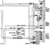
This is the schematic for the pin out of the Aux Sound Power board and the sound board. The Aux Power board is the 7 pin connector and the Sound board is the 12 pin one

DevilsDare sounds Board2.jpg

Now whats got me head in knots is:

Pin 1 for the sound board is supposed to have +12V incoming and Pin 3 is supposed to have -12V incoming.

The +12 comes from Pin one on the AUX sound board and the -12 comes from pin 5.

Now what has me all twisted is that I have the colors of wire that match exactly as according to the above schematic. But the output from the AUX power board at Pin1 is -12 and at Pin5 is +12.

So I figure well those wires just need to switch, I rather have the correct voltage then the correct wire color. So I switch them.

Plug in my new board and the -12 and +12 LED lights don't light up.

so I switch it back and try again with the new board, now all the correct LED's are on but still no sound...

At this point I'm 100% at a loss, I don't think its the sound board, Ive got the brand new one in there and I've got the correct voltages and still nothing

I think at this point I'm going to do all the ground mods, and upgrade the power supply, do the things that is supposed to make this game more reliable and then come back to the sound. Cause my head hurts trying to figure this sound thing out....