The last few days have been pretty boring and I'm jumping back and forth between projects.
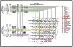
Nothing very exciting to report on Firepower. Just a lot of wiring. But, as promised, here are a lot more photos showing all of the connections I mentioned in the write-ups above.
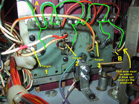
First, let's look at the new 10pt switches behind the drop target banks. At this point you will have completed steps 6-7 in the guide that I linked at the beginning and cut your playfield and fitted the new standups. The photo below illustrates the connections as I've made them:
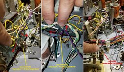
1) The first shot shows the new switch #55 behind the new 1-3 drop target bank. Connection point "A" shows a new WHT/VIO run of wire that has to be added. I will show where this goes to in the next step. Connection point "B" shows a new VIO/GRN wire that we will daisy chain to the other 10pt switch on the other bank and then connect both into the GRN/VIO wire of COlumn 7 on the switch matrix.
2) The 2nd slide shows that other 10pt switch added behind the 4-6 drop target bank. Connection point "C" has a new WHT/BLK wire attached and I will show where that goes in the next step (please note that the guide here calls for a WHT/YEL wire since it has to connect to the same colour wire of Row 4 on the switch matrix. I only had WHT/BLK so I substituted). For the other connection point "D", notice that is has the same VIO/GRN wire that we soldered to "B" on the other switch. B & D can actually be directly linked together (as seen in my new switch matrix schematic earlier connecting switches 55 & 52). As per the guide, both of these connections should be made to the lug with no diode connection. You will now notice a 2nd run of VIO/GRN wire coming from point "D". We will use that to link both of the 10pt switches into Column 7. **NOTE** I added this wire before deciding that I would connect the two switches to switch #49. It would be shorter if you ran it the other way. Meaning, start at "D" then link to "B" and then add another wire to switch #49 (I did the backwards and used a bit more wire as a result)
3) The last slide shows what I mean. You can see the new VIO/GRN wire coming from the top of the image where it is attached to points D and B (switches 52 & 55) and then connecting to switch #49 (Center Middle Standup) where my finger is pointing. It must connect to the same lug as the existing GRN/VIO wire.
Next, let's see where the WHT/VIO and WHT/BLK wires connect.
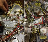
1) On the first slide you can see the WHT/VIO wire we added. It's coming from connection point "A" on the new #55 10pt switch (just beyond the left side of the image) and I've run the wire through the harness, as indicated by the red lines, to get it as close as possible to switch #31 Upper Top Right Standup. Make sure to attach the wire to the same lug that has an original WHT/VIO wire. It should on the non-banded side of the diode.
2) On the 2nd slide you will notice the WHT/BLK wire that is coming from the left. We cannot see the connection point in the photo, but it is the same "C" as in the previous set. This wire needs to run to where I've indicated on the right. It connects to swicth #28 Bottom Right Jet Bumper. Make sure it goes to the lug that has the WHT/YEL wire (again, non-banded diode side)
3) You will also notice a new connection "E". This is for switch #20 which is the new continuous contact switch. It's the last lug on the back of the #3 Target contact plate (the one on the non-banded side of the diode). This wire also needs to go to the same contact point on switch #28 of the Bottom Right Jet Bumper.
Lastly, let's get the final continuous switch from the other bank wired. This is switch #24. See below:
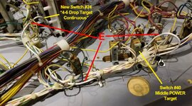
On this image you can see that I've added a new run of WHT/GRY wire and you can just make out where it connects on the far left side to the last contact plate on the back of the 4-6 drop target contact plate. If you still cannot figure out where this is, Please reference my earlier post from a few days ago showing a close-up of the back of the drop target bank. It's the one indicated by "B" in the lower right. ANyway, the red lines show the path I used to run the new WHT/GRY wire over to switch #40 Middle POWER Target. Again, make sure to look for the matching WHT/GRY wire and attach there (it'll be the non-banded diode).
That's it! If you do this all correctly, you should have a pretty clean wiring job.
The only thing left is to run the solenoid wiring for the reset solenoids on both drop target banks.
The guide does a really good job of showing this on step 7 and where to attach two new wires into the existing black Molex playfield connector. You can see that they purposely left the two holes empty when they changed the design of the game at the last moment and the wires were no longer needed. In any case, make sure you get two coloured wires as the guide recommends. Then crimp new male contacts onto each wire and push them into those holes, following the direction of the guide. The image below shows what happens on the playfield since this detail is not in the guides.
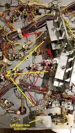
Now, the guide asks for GRY/RED to go to the 1-3 reset coil and GRY/ORG to the 4-6 reset coil. I didn't have these exactly, so the image above shows RED/GRY to the 1-3 bank and YEL/GRY to the 4-6 bank at the top. Here are things to note:
1) The YEL/GRY at connection point "X" is going to the lug on the non-banded diode side of the 4-6 drop target reset coil.
2) The RED/GRY at connection point "Y" is going to the lug on the non-banded diode side of the 1-3 drop target reset coil.
3) A new heavier 18AWG wire has been run in a chain from the banded side lug of the Left Eject Hole Solenoid and daisy-chained to the same lugs on the two new coils. This will provide the necessary power.
I think that about covers my "idiot's guide" to wiring in your Firepower drop target mod
Good luck!

