• We have upgaded to the latest version of XenForum and the process finished without any errors!!!! Enjoy the new forum!

Tim's ROCK thread

tim.sanderson

Active Member
I'll keep this first post short and sweet:

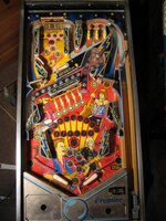
Here I am, still dry, before running the machine out to the truck in the pouring rain.

Here's my buddy Mike and I, now quite wet after running the machine out to the truck in the pouring rain. (did I mention it was pouring rain?) That's Tom on the right.

Tom is a super nice guy, and very happy to chat about pinball and music over a bottle of Steam Whistle. And talk about a gorgeous collection of games!

But for now it's off to bed...
 

Attachments

  • rock1_600px.jpg
    rock1_600px.jpg
    51.2 KB · Views: 467
  • rock2_600px.jpg
    rock2_600px.jpg
    38.2 KB · Views: 470
  • Like
Reactions: WARLOCK

tim.sanderson

Active Member
Re: Tm's ROCK thread

I brought the machine home yesterday. It was sitting in my buddy's underground garage for just over a week.
As it stands right now, it powers up the GI lighting and all zeros on the display, but that's about it. There's no attract mode lighting or sounds, and nothing happens on the screen.
Unfortunately, I have to work today so I won't be able to dig into it until this evening.

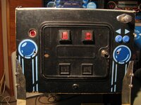
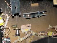
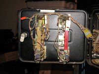
Here are a few quick photos.
 

Attachments

  • IMG_0102.JPG
    IMG_0102.JPG
    141.8 KB · Views: 415
  • IMG_0103.JPG
    IMG_0103.JPG
    126.6 KB · Views: 418
  • IMG_0104.JPG
    IMG_0104.JPG
    101.4 KB · Views: 413
  • IMG_0107.JPG
    IMG_0107.JPG
    103.7 KB · Views: 414

Monkeybug

Active Member
Nov 14, 2012
577
122
43
Stouffville, ON
Re: Tm's ROCK thread

file.php


I always wondered what the girl is holding the band back for? Is there some sort of beauty salon sale going on and she just wants to get to the gig? I guess we will never know.
 

tim.sanderson

Active Member
So I haven't put in as much time into this as I'd have liked to have by now.

After testing the fuses and inspecting the boards (mostly visual so far), I see no obvious reason as to why it won't light up with anything other than the GI, or react to adding credits etc. I can get some of the other inserts to temporarily work when I trigger their respective relays manually. (extra ball, special etc)

I do see there is stuff missing. (no slam-tilt switch and no roller-tilt switch, for starters)

Both wires for each switch are not connected to each other, so I assume that's the same as if they were attached to a switch that was open. I'm not yet sure why the marret connector is used. Although, you know what they say about assumptions...

The red light on the audio is constantly on now, but it was flashing when I first got the game.

I also used to have the score displays lit up with zeros when I first brought it home, now they are off.

So I guess my next course of action is to make sure everything is getting the amount of power they are supposed to be getting.

Any suggestions as to where else I should be checking?
 

Attachments

  • IMG_0145.JPG
    IMG_0145.JPG
    89.8 KB · Views: 349
  • IMG_0140.JPG
    IMG_0140.JPG
    86.7 KB · Views: 347

tim.sanderson

Active Member
spiroagnew said:
You, sir, need a schematic and manual from Steve Young.
Tom gave me the manual when I bought the machine, and I'm headed to Kinko's in the next few minutes to print off a few hundred pages of Sys80 docs. (I know I can read them on my computer, but I prefer an actual hard copy to flip through)

It's times like this I miss the perks of working in the print industry.
 

tim.sanderson

Active Member
Menace said:
If the slam tilt mod hasn't been done yet, start there as it will keep the game from booting...
I'll definitely look into that. Thanks!
I've started systematically going through the 'before powering up' checklist in Clay's guide. I've only checked the coils and 5v power supply so far, but they've checked out OK. Hopefully I can get some more work done on it tomorrow.
 

tim.sanderson

Active Member
This question will illustrate my lack of knowledge in the schematic-reading department. :FP:
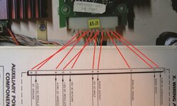
The pins on my AUX PWR board are numbered right to left, 1 to 12. Am I correct in the way I've identified which pin goes to which number on the schematic?
 

Attachments

  • power supply schematic_sm.jpg
    power supply schematic_sm.jpg
    109 KB · Views: 264

brad808

Member
Feb 28, 2013
656
24
18
Brantford
tim.sanderson said:
This question will illustrate my lack of knowledge in the schematic-reading department. :FP:
The pins on my AUX PWR board are numbered right to left, 1 to 12. Am I correct in the way I've identified which pin goes to which number on the schematic?


Looks to be correct. Seems like a terrible way to do the schematics. The board says A5P1 and the schematic says A5P1 so I'd say yes your labelling is correct on the pins. If you blow something up because of my post though I'm going to delete it :lol:
 

Menace

Well-Known Member
Staff member
Nov 14, 2012
2,440
255
83
Santiago de Aurora
Tim, you are correct. Schematics are done this way to avoid a mess of spaghetti, and you will find ALL schematics are like this. If they kept all the connector pin numbers in sequence you would have more trouble tracing lines back from each connector to the components. You'll get used to it.

D
 

tim.sanderson

Active Member
Thanks, guys. I was 99% sure that was the case, but I didn't want to risk a board or two on the 1%. ;)

So it seems all my DC power reads what it should. But when I test the AC, I get a negative value, whether it's testing an AC in or AC out. That doesn't sound right to me.

On another note; I left the machine on when I went to take a shower. When I came back to the machine, there was a slight burning smell. I heard a coil release when I turned off the machine. Upon lifting the playfield, I couldn't find the source of the smell. (no hot coils, nothing looked burnt, nothing felt hot) There's been one or two other times I've heard the same sound when I powered down, but it was the first time I've smelled anything.
 

Menace

Well-Known Member
Staff member
Nov 14, 2012
2,440
255
83
Santiago de Aurora
Ahhh the joys of Sys80... You are probably right about a coil locking on, it's a notorious issue. All of these games have horrendously bad ground paths, and to make matters worse GTB in their infinite wisdom decided to run independent grounds all over the game though connectors no less. As soon as any of these grounds start to "float" due to bad connector pins you end up with phantom lock-on. You will need to do ALL of the ground mods to this game, and for any PF mounted transistors I highly suggest the resistor pull-up mods. Those two things should keep your coils from locking on.

Did you check the coin door slam switch yet? ;)

D
 

tim.sanderson

Active Member
Menace said:
Did you check the coin door slam switch yet? ;) D

I forgot to confirm this in an earlier post;
Yup, it seems like the slam mod has been done:

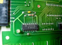
When I compare pics of a totally ground modded Sys 80 and mine, it it looks like only some of them have been done. I'll post some detailed pics of the boards in the back box very soon.

As for the connectors, I've been thinking the ones I have may give me problems. Some of them are pretty dried out. I've been testing them to make sure there's continuity from the wire to the pins.

Menace said:
Ahhh the joys of Sys80...
I asked for a challenge. Looks like I found one!
 

Attachments

  • slam_mod_1.jpg
    slam_mod_1.jpg
    137.3 KB · Views: 220

Menace

Well-Known Member
Staff member
Nov 14, 2012
2,440
255
83
Santiago de Aurora
One of the most important and overlooked ground mods is the one in the lower cabinet. You need to tie all of the discreet ground lines together after the connector. (the side of the harness closest to the back) There should be two of these, a 4 wire and then I think a 9 wire? It's been a while since I've done one of these...

D