• We have upgaded to the latest version of XenForum and the process finished without any errors!!!! Enjoy the new forum!

TZ problem, can you help?

ALJO

Active Member
Apr 6, 2013
388
76
28
St.Romuald
Hey everyone.
I just turned my TZ on this morning and noticed that the pop bumpers were'nt working, I searched for a broken wire but nothing, after a little investigation I found out that every switch that has a green/orange wire connected to it was not working, so that's the 3 left inlane and outlane switches, the 2 slingshot switches and the 3 pop bumpers. When I start a game, if I manuall activate all of the switches one after the other, there will always be 1 coil that will activate (slings and pops) but after, nothing, I have to turn the game off and on again and start another game to be able to activate another coil manually.
I went into test mod and slings and pops work great, it's in single switch test mod that something weird happens..... is'nt there supposed to be only one spot per switch activated? check the video, there is one whole line of switches activated and if I press each of the pop bumper switches, it's a whole line that lights up.
Can anybody give me a hint as to what is wrong here?
Thanks.
 

ALJO

Active Member
Apr 6, 2013
388
76
28
St.Romuald
I found this on Pinwiki, what do you think?
Since it's one whole row (green/orange) in the Switch matrix that is blown, maybe it's a CPU chip?

The Chips that Control the Switch Matrix.
The switch columns are controlled by a single 18 pin ULN2803 chip on the CPU board at position U20. The switch rows are controlled by two LM339 chips on the CPU board at positions U18 and U19. The direct switch rows are controlled by two LM339 chips on the CPU board at positiion U16 and U17. These chip designations apply to all WPC generations.

On WPC-S and WPC-95 games, the ULN2803 that controls the switch columns on the CPU board is socketed. On all other WPC games up to 1994 this chip is not socketed. When a series of switches goes out, it tends to be the ULN2803 at U20 (all WPC revisions) that fails. Williams recognized this, and started socketing this chip with WPC-S. On WPC-S CPU boards, the ULN2803 chip is underneath the battery sub-board. ULN2803 is equivalent to NTE2018. If U20 dies "hard", it could also blow the 74LS374 at U14 (on WPC-95 it's U23, a 74HC237) on the CPU board.

The LM339 chips that control the switch rows at U18 and U19 (all WPC revisions) tend to fail less often. LM339 is equivalent to NTE834. There are also two more LM339 CPU board chips at U16 and U17 (all WPC revisions). These two chips control the direct switches (coin door, diagnostics, etc). These do not fail often either.
 

dr.nybble

Active Member
Nov 28, 2014
125
49
28
Ottawa
Pinwiki has instructions for testing the switch matrix with the connectors unplugged, to check whether it is a problem on the MPU. Try that, from ‘Isolate the problem to the MPU or to the game wiring/diodes/switches’
 

ALJO

Active Member
Apr 6, 2013
388
76
28
St.Romuald
Thanks.
Is that a link you tried to post?
I can't find the page on Pinwiki that your talking about.
What I tried is I disconnected J5 from the Custom opto board (SW10) and did the switch test again and I have the same results/problem, so do I have to conclude that the problem is on the CPU ?
 

dr.nybble

Active Member
Nov 28, 2014
125
49
28
Ottawa
You could go further and look at the signals from the LM339 with a logic probe or oscilloscope; or buy socket + chips and replace.

Also inspect the board to see if there is any battery damage!
 

ALJO

Active Member
Apr 6, 2013
388
76
28
St.Romuald
Thanks for all of your help Dr.nybble, I could'nt have done it without you.....
I read very closely and I found this at the end: Quote:
"If multiple switch closures are reported when you touch one pin of the connector, or if the CPU reports a row or column short, then there is a fault with the switch matrix circuitry on the CPU board itself. Be aware that an additional fault may still be present on the playfield. Switch matrix chips do not simply blow for no reason!"

So I went and searched for a short between a coil wire with a switch wire of some sort......I had bought a flasher mod for the slings (they are connected to the coils) that had flahing lights when the bumpers were hit, well the 3 LED's under the sling plastics are inter connected with a wire form that is not isolated, when one of th balls came and hit sling hard enough the switch leaf went and touched the wire form and blew the U20 chip. so not only did I find the cause but I also know what part of the CPU is wrong because that CAN cause to blow a chip according to this quote:

"One fairly common reason that a ULN2803 or other switch matrix circuitry may blow is a short to coil power. In the picture at left, the coil that actuates the "Bridge Diverter" on the game Twilight Zone, is touching the coil bracket on one side. Since coil power is present at both coil lugs (which is normal), a coil lug touching metal will conduct coil power to that metal. In this case, the coil bracket touches the bridge diverter piano wire and then the coil diverter and then the entire wireform. If a switch matrix solder tab or switch blade metal shorts to the wireform, poof! Get ready to replace the ULN2803."
 
Last edited:

ALJO

Active Member
Apr 6, 2013
388
76
28
St.Romuald
I already bought the chips so all I need are the sockets but I found these for cheap, 10pcs of each:
 

ALJO

Active Member
Apr 6, 2013
388
76
28
St.Romuald
My switch problem is fixed, thanks to your help.
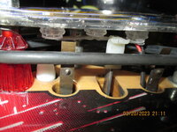
This is the mod I bought: flasher lights activate when ball hits the slings, these are 50V bulbs that are connected to each sling coil, the switch went and touched the wire form that relates the 3 bulbs together under the slinfshot plastics and "boom", the ULN2803 chip (U20) blew.
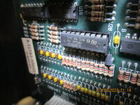
I put a socket on U20, so if it happens again, I'll just replace the chip, I don't think it will happen again because I applied epoxy glue on the wire form under the slings.
If anyone wants a ULN2803 chip or a 74LS374 chip, let me know, I bought 10 of each and 10X 18 pin sockets and 10X 20 pin sockets, so If you need those as well, no problem.
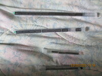
I posted a picture of the finished job as well.
 

Attachments

  • IMG_9691.JPG
    IMG_9691.JPG
    156.8 KB · Views: 5
  • IMG_9694.JPG
    IMG_9694.JPG
    158.4 KB · Views: 5
  • IMG_9690.JPG
    IMG_9690.JPG
    152.2 KB · Views: 5

good_buddy83

Active Member
Dec 19, 2012
200
42
28
Beamsville
Great fix! That is a tough one, I had the same issue on a CV. If someone else comes across this issue, I highly reccomend checking your stand-up targets for broken riviets. In my case, a broken brass rivet backed out a bit and touched a bracket. It just so happened that the ring master's head flasher wire was worn and touching the bracket. Poof, same issue! Wicked frustrating. I went through 3 ULN2803's before I figured it out. Highly reccomend socketing that chip, exactly what you did. Well done.
 
  • Like
Reactions: ALJO