• We have upgaded to the latest version of XenForum and the process finished without any errors!!!! Enjoy the new forum!

Creech Hologram LCD Mod

mwong168

Administrator
Staff member
Nov 14, 2012
6,680
1,450
113
46
Toronto
logo.png


I have been following this mod for well over a year when Pinball Mike D announced it on pinside. I thought it looked great and said to myself that if I ever got a Creech I am for sure going to get one of these kits. Even though I hadn't found myself a Creech yet I signed up to be on his next pre-order last summer. I get my Creech last November and few weeks later I get a PM saying the next round of pre-orders will be filled in December... perfect timing :)

Anyways, I had my kit shipped together with my good pal bigbossfan who also just drove 1800kms round trip to get his Creech too. Unfortunately his game is in pieces right now and in the middle of full out shop job but he is looking forward to getting it back together and working with this mod. I was finally able to connect with him last week when I went up snowboarding and picked up this kit and a bunch of parts we split shipping on as well.

15784388654_43a6ec3628_b.jpg


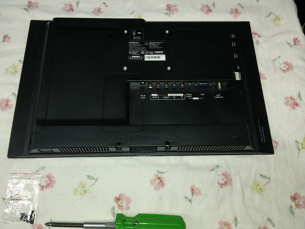
The kit included everything you need such as machine screws, washers, zip ties, etc... You can definitely tell someone put a lot of thought and care putting all this together.
16220958077_ceef0231c6_b.jpg


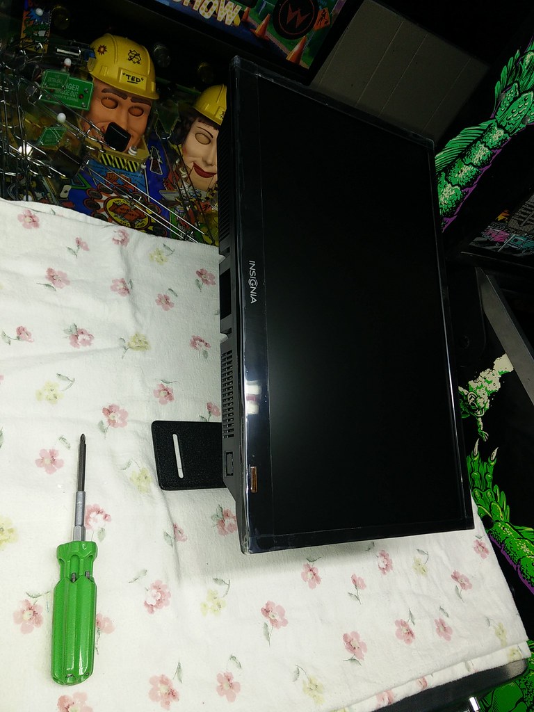
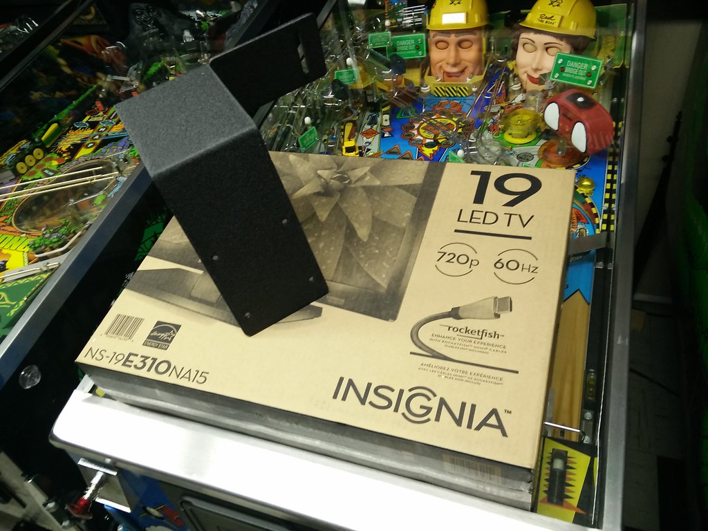
The kit also comes with this very sturdy black powder coated mount for this 19" LED TV I picked up on sale a few weeks back at a local Best Buy for $99.
16406863535_c80299c75c_b.jpg


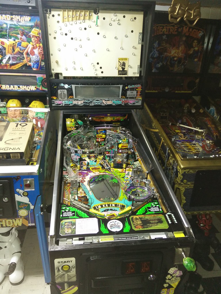
Now let's get started with the install and remove the playfield glass, translite and balls from the machine so they don't fall out when we lift the playfield up.
16406867535_8a5c958ce0_b.jpg


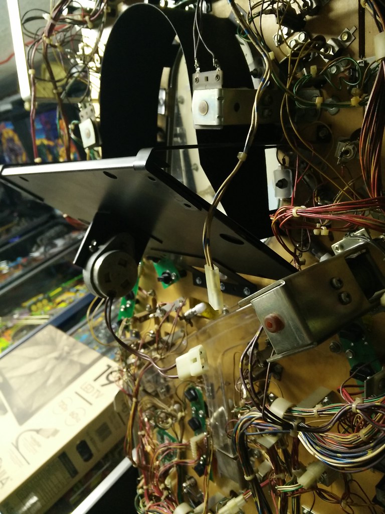
Once you lift the playfield up you need to locate the connector for the motor behind the hologram. Disconnect it and secure it with a zip tie to the nearest game wiring harness so that it isn't just dangling.
16219461110_2d8bf3c8a3_b.jpg


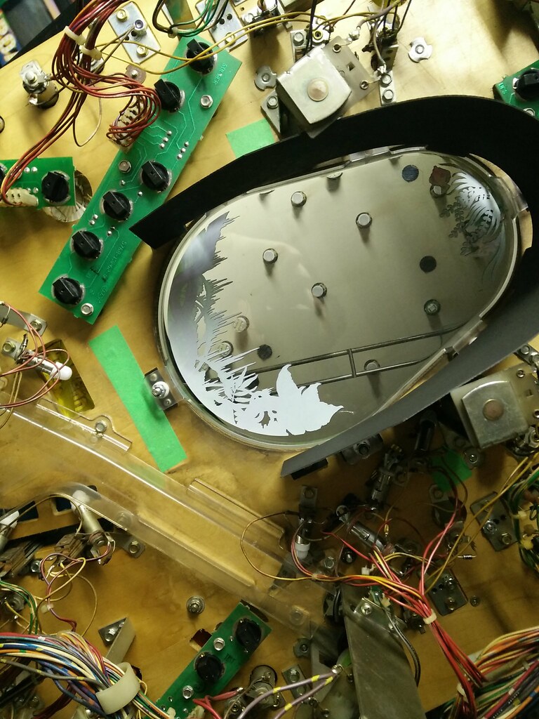
There are five screws in total holding the hologram bracket in placeunder the playfield. There is one on each support arm and three in a row on the very bottom. I used some painters tape as per Mike D's suggestion so that no wood dust would shake loose from these holes left behind and fall onto the LCD screen.
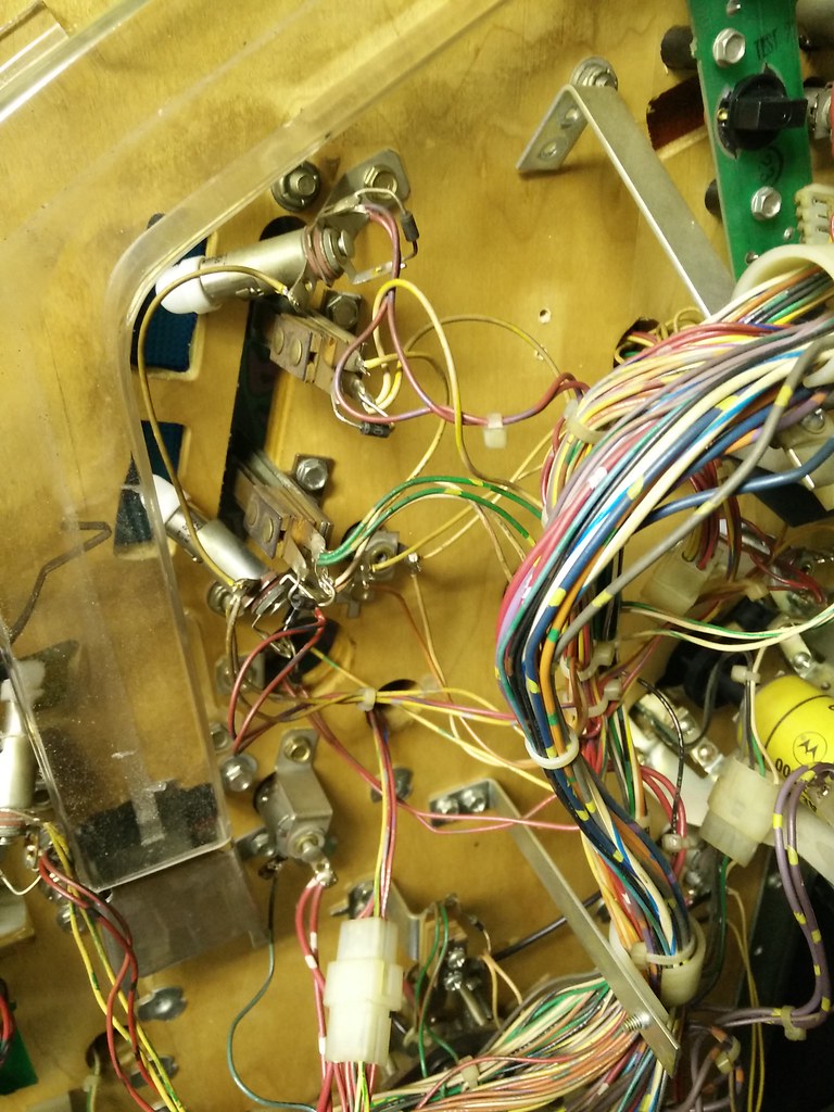
16219236108_1f3d95221b_b.jpg


Now we have to remove some wire harness stand up supports from under the playfield so that they do not hit the LCD screen when the playfield is put back in the down position. The first stand up is locate to the right of the snack bar scoop hole and behind two of the menu target stand ups.
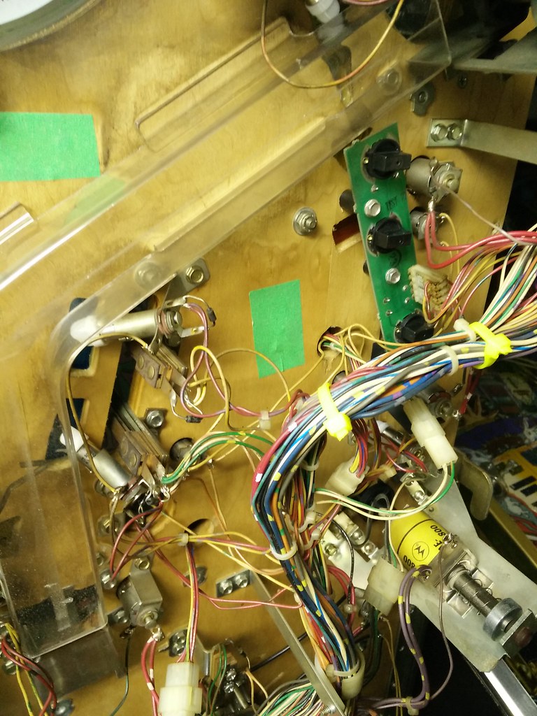
16406875555_b57c1fa7c8_b.jpg


I used two bigger zip ties on each side before I remove the stand up and used some painters tape to cover up the screw holes left behind.
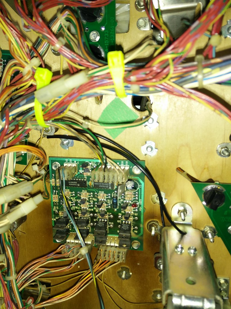
16223812789_54a79bacbc_b.jpg


The other stand up that needs to be remove is just above the chase lamp board next to the pop bumper.
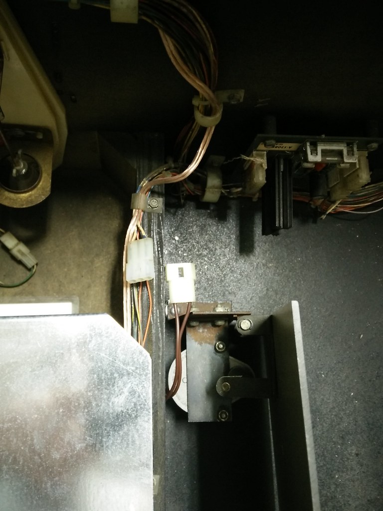
16220963437_271682199e_b.jpg


Now in the lower cabinet locate the connector for the mirror motor and disconnect it before you start to remove it. It should only be held in with two machine screws and some washers.
16406865515_611d832c99_b.jpg


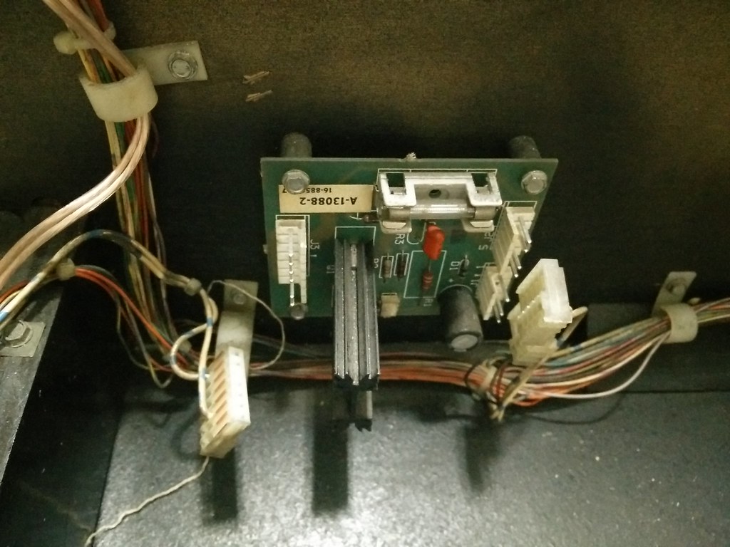
If you trace the connector from the mirror motor it should lead you to J3 on the triac driver board. I removed this connector from the game instead of leaving it dangling inside since it is no longer used. Then I disconnected J1 and J2 on the other side of the triac board before I started to remove the four screws securing it to the cab.
16220968387_f7cd99b1d4_b.jpg


16219457910_396d730b56_b.jpg


Now I temporarily laid Mike D's new board close to where it will finally be mounted on the side of the cab and proceeded to run the wiring harness up to the head.
16405947232_1dbdccb0be_b.jpg


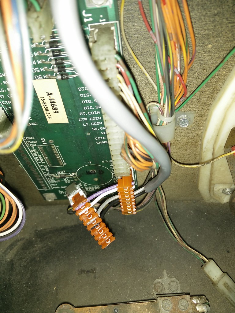
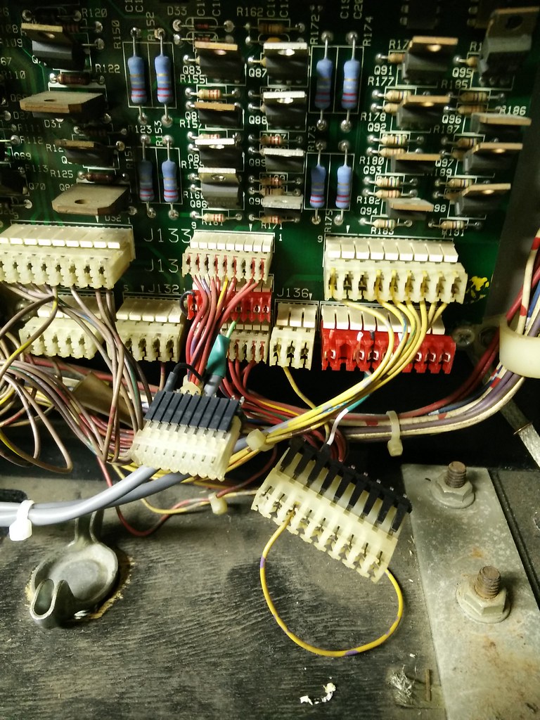
The harness from the mod taps into J134 and J138 on your power driver board. All you have to do is disconnect them, connect the red connectors from the new wiring harness and then you should be able to piggy back off each one as shown above. Once these connections have been made you are pretty much done up here. You can tidy things up by running the new wiring harness through the existing holders in the cab or you can use some zip ties to carefully secure onto the existing wire harnesses.
15784412294_be2d73e5ed_b.jpg


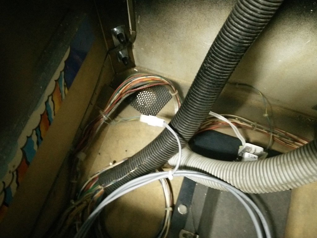
The next tie into the game from the new harness can be found near the very back of the cab. There should be a connector that can be traced from the bulb to the game's main harness. Disconnect it, plug it into the new wiring harness and don't worry about which direction as it can only be plugged in one way. If you actually manage to physically in the wrong way then kudos to you ;)

16219450570_118c61261d_b.jpg


Now that I have all the proper tie ins to the game I am ready to mount Mike D's board to the side of my cabinet. Now this will probably vary from everyone's game in terms of how your original triac board was mounted because some might be higher or lower. I opted to use existing two top holes in the cab for the bottom of the new board and I made two new holes for top. The reason for this is because I wanted to have easy access and enough clearance to unplug and plug the USB flash drive in case I wanted to change videos or images. Otherwise Mike D's board lines up perfectly with the existing holes for those who are worried about making new holes on their precious game :p
16405946402_49f912d0d0_b.jpg


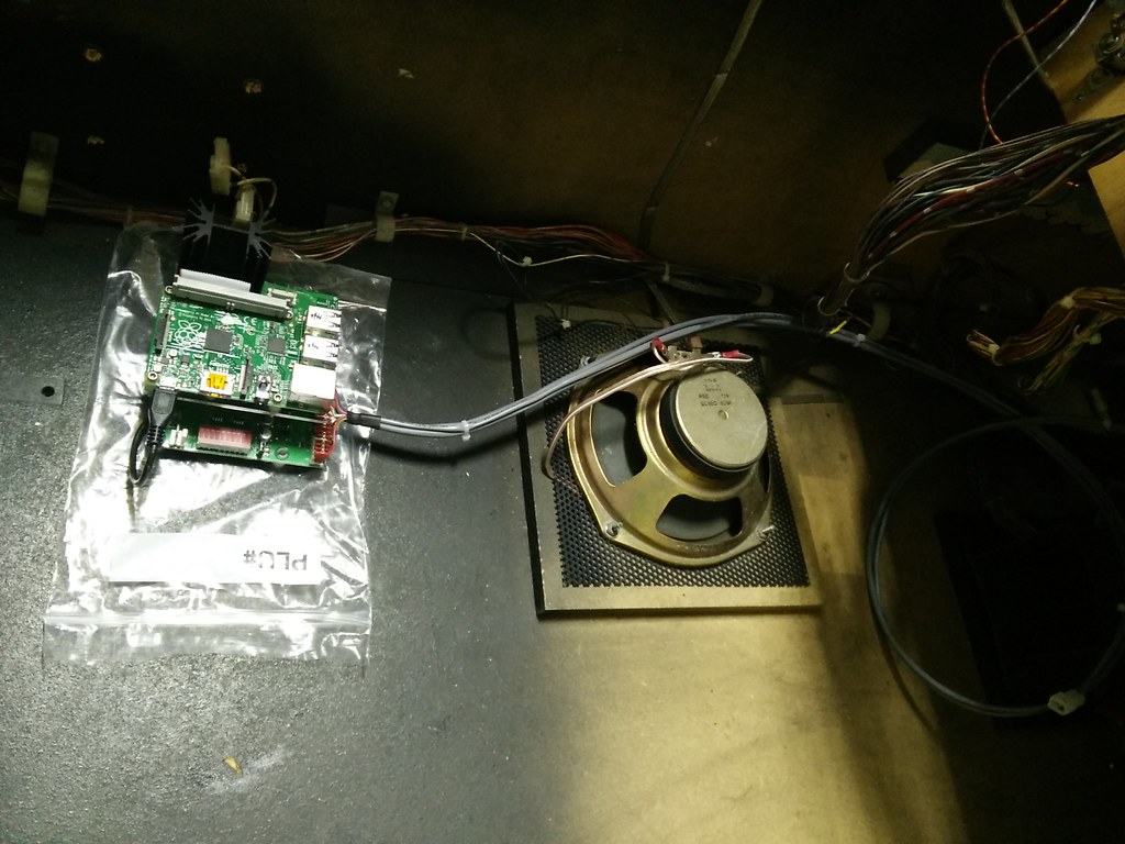
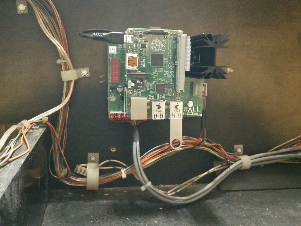
One last connection needs to be made to the new board just below the big heatsink so the board gets power. Locate the J1 connector we disconnected earlier from the mirror motor triac board. I had to replace the old IDC connector and re-crimp with molex as one of the wires popped out. If anyone is interested I can show you how that was done in a later post. Anytime you need to replace an IDC connector always use molex as it provides a far superior connection. Since you have easy access to everything you might as well take this time to insert the microSD card into the Raspberry Pi, USB flash drive and make sure the micro USB connector from Mike D's board is connected too.
 

mwong168

Administrator
Staff member
Nov 14, 2012
6,680
1,450
113
46
Toronto
16406876455_859e6d50e8_b.jpg


16380886326_c2c2bb78af_b.jpg


I love opening new toys and after unboxing the Insigna LCD I located the four mounting screws located inside the instructions bag. Then I removed the lower part where the stand is supposed to attach held on by two screws so it doesn't interfere when I install the LCD into the game.

16219470060_e013318514_b.jpg


16380907366_bdcb00ab4d_b.jpg


I mounted the LCD to the stand provided by Mike D and pay attention to the orientation or location of the Insignia logo is once flipped over. If it is the other way then your videos and images will be upside down when installed in the game.

16219230948_d5e7e335bf_b.jpg


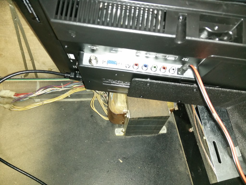
Before securing the LCD into the game now would be a good time to connect the HDMI cable and power connector. It doesn't matter which HDMI input you select because you can set which once later once you turn it on.

16219454030_00af9fd5ef_b.jpg


Using the two machine screws and washers supplied in the kit I mounted my LCD closest to the piece of wood that the coin box rests up against. You can adjust this later if you are not happy with the viewing angle during game play. I noticed this newer revision of the mod has an open slit for the mounting screws instead of three fixed holes. This should make fine tuning the viewing angle much easier and give you a lot more flexibility. As per Mike D's I used a measuring tape to make sure the left side of the LCD screen is not more then 3.5" from the left side of the cabinet. The reason is because the coil bracket for the VUK for the right inlane is very close by and you don't want it making contact with the LCD.

16406863135_d3eb731339_b.jpg


This is the final tie inso the LCD screen gets power and comes on when you turn the game on. Locate the J2 connector on the coin door interface board located next to the tilt bob. Remove that connector and plug in the connector from the tv power wiring harness and then piggy back the cabinet J2 connector.

16380898186_e0f367a8db_b.jpg


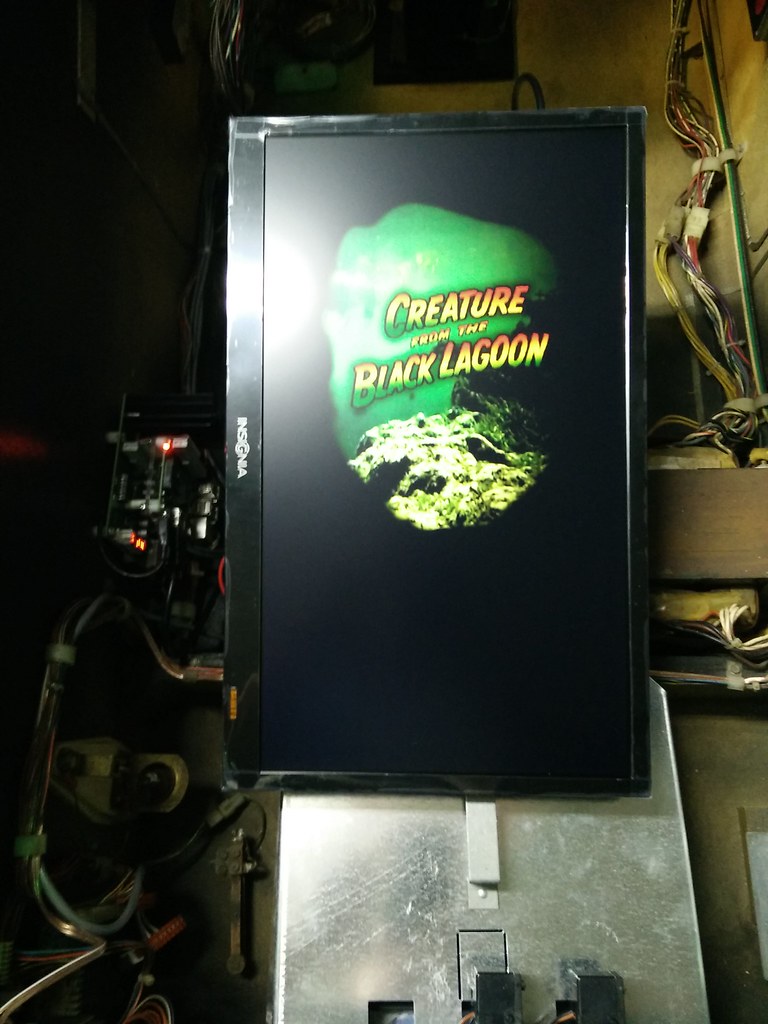
I double checked all my connections and made sure I didn't knock any existing wiring loose such as a wire from a light socket touching a coil. Now the moment of truth and it's alive after 30 second boot up of the Raspberry Pi and setting the tv's input to HDMI #1.

16406890995_39d69e1280_b.jpg


I carefully lowered the playfield while looking through the coin door to make sure nothing is touching or hitting the LCD screen. The position of the LCD is perfect for where I like to stand when I play my games. Since I had the playfield glass off I loaded the balls back into the game to start it. I used my hand to trigger certain things such as spelling F-I-L-M and a different image showed up for each letter, started multi-ball and found the creature to see the new video animation as well as Mega Menu to see another cool animation.

Thanks to Mike D for making this awesome mod and spending the time making/editing all these animations and images which really add to the game play interaction and atmosphere.

16380892686_51b95a978c_b.jpg


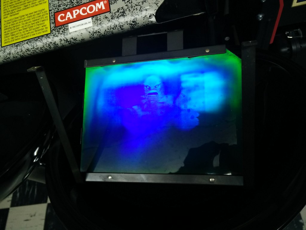
For anyone who has a hologram that looks blue like this I highly recommend getting this for your game. Here is a video that Mike D created showing how it works:


mwong168

Administrator
Staff member
Nov 14, 2012
6,680
1,450
113
46
Toronto
Now my install didn't go quite as smooth as I documented above but it had nothing to do with the mod itself but there were a few connectors on my power driver board incorrectly by the previous owner. After I powered up the game to see if the LCD mod worked I noticed that all of the insert lights in the lower playfield like FILM and KISS were not working. It was nearing 1am as I was installing this and had work the next day so instead of digging deeper I just called it a night.

So the next day at work I was trying to retrace my steps prior to installing the mod and figured the issue had to be on the power driver board connections since all the connections I made inside the lower part of the cab were not related to the lamp matrix.

16403486045_d8175e3d4f_b.jpg

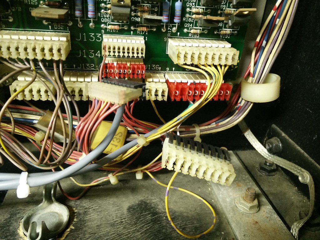
When I was making the connections the night before I noticed that J137 and J138 were switched around. I was a bit puzzled at this point at how the game was working fine before but after exchanging a few messages with Menace he confirmed that these connectors can be interchanged as they are run in parallel. Using the picture below as reference, the current connector in J137 was in J138 and the connector with the single wire in pin #3 was in J137.

16219226438_f32c79b3e0_b.jpg


It was also obvious to me because looking at the new wiring harness the "Z" piggy back connector only had a single wire on pin #3. So had I piggy backed the other connector a lot of the wires would have no where to go. So the next day at my work I started thinking in my head that could be one of the possible reasons why my insert lights stopped working. Perhaps a wire had popped out of one of the IDC connectors or maybe one of the pin headers or traces were bad on the power drive board which was why the connectors were reversed in the first place?

So not being 100% convinced it was J137/J138 I continued to dwell on this some more at work whenever I needed a break. I then decided to look at the game's lamp matrix and maybe when I was removing the wire holder stand offs from under the playfield I may have broke a common wire in the chain?

16216137550_0aabac901a_o.png


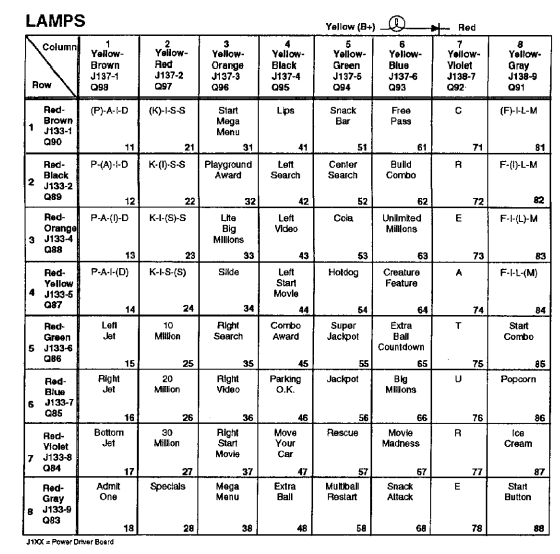
Let me give you some examples for those who haven't had to diagnose lamp or switch matrix issues before. For example if all the lamps in row 1 were out they all have Red/Brown wire in common, so if a break was to occur somewhere in the chain it could potentially knock out the entire row. Another example would be if all the lamps in column 4 was out then there might be a problem with Yellow/Black wire.

In my case the inserts I had out on the playfield didn't exactly correspond to a particular row or column as shown in the lamp matrix. I was pretty careful when I working under the playfield so chances of me knocking out all these common wires was slim to none. So I decided to focus in on some other connectors I touched on the power driver board. If you look at each row and column above you will see that the corresponding connector is listed along with the drive transistor (Q##). That was another possibility is a short somewhere taking out the transistor. This could happen if there is a short or working on a game with the power turned on which I don't recommend by the way unless you absolutely have to. I know people do this all the time when they are adding LEDs to their games and by accident they happen to short out a light socket or touch something live with their screw driver. Most of the time it just blows a fuse but I have heard stories where people have taken out their MPU completely along with 2 DMDs :eek:

Then suddenly I found the issue and if you scroll up to the last picture have a look at the connector J133. Now look at the lamp matrix rows and you will see Row 1 J133-1 is Red/Brown, J133-2 is Red/Black, J133-3 is Red/Orange, J133-4 is Red/Yellow and so forth. Son of a bitch another reversed connector and this one wasn't as obvious as the J137/J138 since the connector all lined up with the piggy back. So another quick message to Menace to confirm if J133/J134 could be interchanged and he said yes theoretically they can be and J135 can be too as they are all parallel. The game can still work but he also said in the past he has seen switched connectors cause some weird issues on his client's games. You see even though connectors are keyed it doesn't help in this case when they are all keyed the same! At this point I'm sure you can also use the wire's memory from being in the same position for nearly 20+ years to line up to the proper connector but in this case it didn't work for the previous owner of my game. That is why whenever I remove connectors I temporarily label them with masking tape or take pictures so I can verify later.

It's a good thing I took lots of pictures so I was able to back track what I did the night before at work. Menace was laughing real hard when I figured it out because he knew it was only 12pm and I don't get off work till 5pm and likely with traffic I won't be home till well past 6pm to swap this connector to see if it fixes things.

16405947232_1dbdccb0be_b.jpg


Well I got home by 5:47pm and went straight down to swap connectors and voila everything was all good again. I'm pretty OCD when it comes to issues with my games and I swear even my wife has threatened to kick me out of bed because I will be tossing and turning until SB opens the next morning so I can get the parts I need to fix it :D
 

Chris Bardon

Well-Known Member
Nov 15, 2012
1,342
182
63
Mississauga, ON
Thanks for the detailed writeup-definitely a cool mod. Pricey, but I like the way he's added more feedback to the LCD besides just the creature image. If the game is a keeper, why not add something like this?
 

mwong168

Administrator
Staff member
Nov 14, 2012
6,680
1,450
113
46
Toronto
I've had maybe one full game with it since installing it really late last Thursday night. I really like how it looks so far and some people asked me if it is distracting to have something displayed in the window at all times. I don't find it distracting at all and to be honest it is better then staring at a black empty window most of the time and better then a ColorDMD because you can actually see it while playing too. I do love how the dots look on ColorDMD for Creech but given that six of my games have with full color support I don't think I want to go down that slippery slope. This LCD mod alone set me back about $630cdn after it was all said and done thanks to our shitty exchange rate.
 

Beafraid

Active Member
Dec 13, 2012
519
60
28
56
Maple
Great mod. I found it very easy to install. I wish there was a way to adjust the tv though as for me it would be nice to have it move towards the head of the pin a bit to centre what you see in the window.
 

monty

Member
Jul 30, 2014
76
18
8
Ottawa
holy crap. great writeup and pics man! well done. had the chance to play one with this mod a few weeks back and it looks really cool. way better than a faded blue/purple blob of a Creech.
 

mwong168

Administrator
Staff member
Nov 14, 2012
6,680
1,450
113
46
Toronto
Great mod. I found it very easy to install. I wish there was a way to adjust the tv though as for me it would be nice to have it move towards the head of the pin a bit to centre what you see in the window.

Why can't you adjust yours? It should be as easy as loosening these two screws, sliding the LCD mount back towards the head and tighten.

16219454030_00af9fd5ef_b.jpg


Unless you got a earlier revisions of his mod which had three fixed holes instead of a open slit for mounting the LCD.

16427767725_fa5f459701_o.png


I am probably going to slide my LCD about 1/2" back towards the head.
 

Beafraid

Active Member
Dec 13, 2012
519
60
28
56
Maple
The screws are right at the top and bottom of the slot. There is no wiggle room to go either way which I find odd as I figured the purpose of a slot was to allow adjustability. I guess I could just move it and screw in the screws where ever they land.